 |
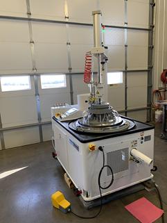
| Speedfam 9B Rebuilt |
|
|
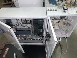 |
| Speedfam 9B Rebuilt |
|
|
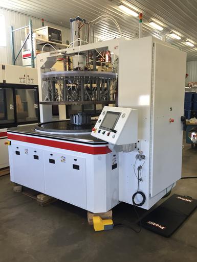
Speedfam 9B Double Sided Lapper
9B single motor machine with updated controls.
|
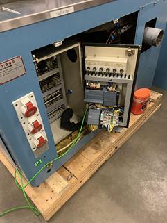 |
| Speedfam 9B PLC Change |
|
|
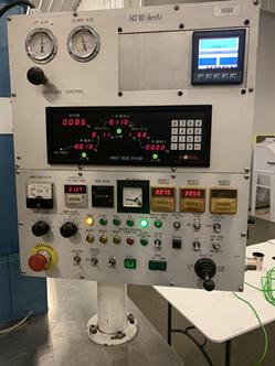 |
| Speedfam 9B Control Panel |
|
|
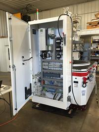
Speedfam 9B PLC Change
Replaced the Omron PLC with a new Siemens S7-1200.
Sony display and other items on the control panel were replaced.
|
 |
| Speedfam 16B Spindle Rebuilt |
|
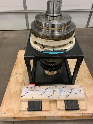
| Speedfam 16B Spindle Rebuilt
Older 16B Spindle Rebuilt.
|
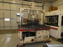 |
| Speedfam 20B Before |
|
|
 |
| Speedfam 20B After |
|
| Speedfam 20B Double Sided Lapper
20B single motor machine with updated controls and added ring gear motor and drive.
|
 |
| Speedfam 22B |
|
|
Speedfam 22B Double Sided Lapper
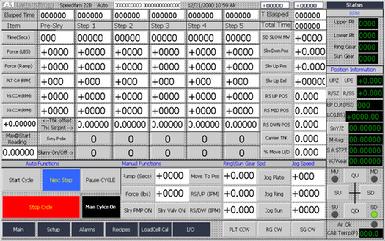
The 22B Software (additional details can be provided):
-
Brief overview
-
Time – The time is entered in Seconds and the following limits apply.
-
Pre Slurry – 0-999 seconds
-
Step 1 to 5 – 0-99999 seconds.
-
Total time of all steps is approximately 139 hours or 5.7 days.
-
Force – Downforce in lbs. This value comes from the loadcell which is attached to the sub cylinder. The PLC reads the loadcell directly and is calibrated through the screen.
-
Force Ramp – in seconds
-
Pre Slurry – 0- 60 seconds
-
Ramp Limits Steps 1 to 50 – 0-60 seconds.
-
(V2 and Later Software)The force ramp affects the Sony probe. During Force ramping the Sony will be disabled until the force ramp has been completed plus the Comp Delay. If the force ramp is set to 5 (Seconds)and the comp delay variable is 1000 ms the total time before the Sony will be enabled is 6000ms or 6 seconds. This change was made so that no matter what the force ramp the Sony would not engage until after the ramp was completed. This made the initial Sony reading more accurate.
-
Plate Drive Speed, remember this also controls the upper plate speed (on this particular machine).
-
Ring Speed – Controls the rotation and direction of the ring gear.
-
Sun Gear Speed – Controls the sun gear speed
-
Thickness Setpoint – The target thickness sets the value that the Sony or linear scale should not go below if a reading goes below it jumps to the next step. Each steps thickness setpoint can be set to the same or a different value. The thickness offset can be changed if the Sony reading is not corresponding to the actual thickness of the part. The Thickness offset is a global variable and is not saved in the recipe. This value is sign value as well so it can be +/-. This value was added so that if for example the part thickness is not coming out to the correct thickness measured on a calibrate gauge the thickness can be adjusted without changing all the recipes used. This function will be described again in more detail. There are also options when reading the probe during processing. In the setup screen provides other options such as enabling averaging.
-
Slurry 0/1 – This controls the ball valve which supplies the slurry to the upper plate. When on slurry moves through the manifold blocks and to the upper plate when off it goes back to the tank. Optional blowoff can also be provided which is used to clear out the lines at the end of the process this helps prevent lapping compound from settling in the fittings and or lines and clogging them.
-
Sony Probe/Linear Scale button – The Sony probe is the primary thickness measurement device which is more accurate than the linear scale which is attached to the upper plate. If this button is pressed than the linear scale is used for thickness measurement during processing. This setting is saved with the recipe if it set with Sony being displayed than the Sony will be used if set with Linear scale displayed than the linear scale is used.
-
Linear Scale – The primary function of the linear scale is the position of the upper plate. This allows setting in the recipe the ability to change the downforce during the “Slow Down” move. It can be used instead of the Sony Probe by pressing the button the Linear Scale will display and the process will be run off of the linear scale.
-
Ring/Sun Gear Position - The ring and sun gear up/down position can be saved and adjusted per the recipe. The recipe also allows the sun and ring gear position to changed each cycle preventing grooves to be worn in the ring and sun gear when using thin blue steel carriers.
|
 |
| Speedfam 22B Software |
|
|
|